The calibrated backscattered measured by a SAR sensors is described using Radar Cross Section(RCS) σ, which is defined as the ratio between the received and incident signal intensity.
σ = Ireceived/Iincident . 4πR2[m2]
The RCS is not usually easy to interpret, being influenced by both sensor characteristics and properties of the features. The most important feature properties are
- Surface roughness, hr which determines how much of the scattered signal is directed back to the sensor
- Dielectric properties quantified by its complex relative dielectric constant, εr which determines the penetration of signal into the surface.
While Surface roughness and dielectric property are parameters of earth features, the amount of energy scattered back to the sensor and the penetration depends on the wavelength of the sensor λ and the polarization of the signal. Generally, the longer the sensor wavelength, the deeper the penetration depth. For most features, the short wavelength such as x-band scatter at the surface while longer wavelength such as C and L-band penetrates deeper. To quantify the penetration depth, knowledge of dielectric property εr of the medium is required. The penetration depth, pd, can be approximated as
pd = λ√ε’r/(2πε”r)
Where ε’ is the real component (dielectic constant) and ε” is the imaginary component (Loss factor) of the complex relative permittivity. Both are strongly dependent on moisture content of the feature. The following insights are derived from the equation:
- Longer wavelength (smaller frequency) means more EM wave penetration
- EM wave penetration increases as dielectric constant dielectric constant increases
- EM wave penetration decreases as loss factor increases
As moisture content in an object increases, the loss factor generally increases. Therefore, penetration depth decreases with increase in moisture content.
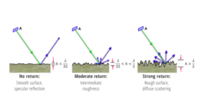
Besides dry soil and snow, most earth surfaces allow little penetration for microwave radiation such that surface scattering dominates the measured backscatter. Surface roughness is the driver of this behaviour. But again, the roughness of a surface is relative to the wavelength of the sensor. Fraunhofer posited that a surface is considered rough if the height deviation exceed the value of hr which is determined by the expression:
hr › λ/(32cosθ)
The dependence of surface roughness on λ indicates that a rough surface relative to x-band might not be rough with L-band.
The figure below show a schematic illustration of surface roughness from smooth to rough and the corresponding backscatter (blue). As can be seen, smoooth surface deflects much of the radar energy away from sensor while rough surface has more backscatter in the sensor direction corresponding to higher RCS. Wavelength dependence also means that surface will appear increasingly darker as the wavelength increases from X-band through C-band to L-band since the roughness will decrease relatively.
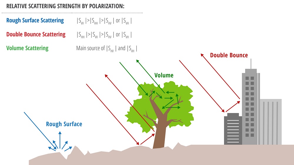
The backscatter from earth features also depend on the polarization of the signal. Col polarized SAR system transmits and receive signal in same direction (HH or VV). Cross polarized signal transmits in one direction and receive in another direction (HV or VH). A SAR system could be single polarization in which case it has just one polarization (HH or VV), dual polarization having HH and HV or VV and VH or HH and VV. There are also quad polarization configuration also referred to as full polarization where the system has all polarizations -HH, VV, HV and VH. Generally, earth features can be considered to be a combination of three types of scatters :
- Rough surface scatters
- Double bounce scatters
- Volume scatters
These scatters reflects radar energy differently for different polarizations.
For rough surface scatters such as bare soils; VV > HH > HV (or VH).
For double bounce scatters such as buildings; HH > VV > HV (or VH)
For volume scatters such as vegetation; HV and VH > VV or HH
Appropriate combination of polarisations can enhance feature interpretation and insight. For RGB combination, a plausible combination is:
Red (HH) for double bounce scatters(buildings)
Green(HV) for volume scatters(vegetation)
Blue(VV) for rough surface scatters(water)