Besides the crucial merit of all-day and weather observation capability, radar systems interact with earth features differently than other imaging systems thereby providing additional information that would otherwise be impossible to derive. While optical and thermal sensors records the solar irradiation reflected or emitted by earth features, radar systems records the surface characteristics related to roughness or dielectric properties. Consequently, optical sensors can be used to monitor snow cover area (SCA), radar sensors can also be used to monitor SCA as well as other properties such as grain size, density, wetness etc. Additional advantage of radar sensors is obtained from the phase information and polarizations. This will be further discussed in subsequent posts. This post is dedicated to the geometry of Side Looking Airborne Radar (SLAR) systems.
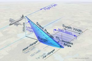
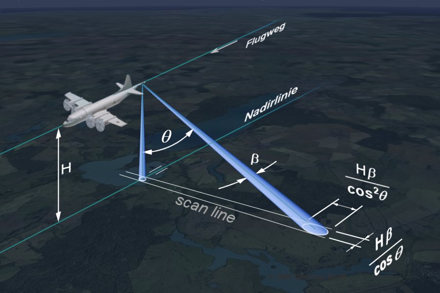
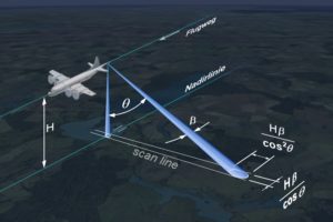
The configuration of a SLAR system mounted on an aircraft is shown in the figure 1. The aircraft moves forward along its line of flight at an altitude H with its nadir directly beneath the platform. The sensors of optical systems look towards the nadir but SLAR have their antenna tilted at an angle away from the nadir (refer to as look angle Ø) such that they can illuminate a continuous swath on the ground as the aircraft moves along. The azimuth is the along-track dimension parallel to the line of flight while the range is the across-track direction perpendicular to the flight direction (and nadir). The strip of the earth surface over which data are collected by SLAR is the Swath. It is the width of the imaged scene in the range (across-track) direction. The extent of the the swath depends on the motion of the aircraft along-track direction.
 SLAR system transmits a sequence of short microwave pulses of pulse length Lp as it flies along its track. Each pulses illuminates an instantaneous area on the ground known as antenna footprint. The size S of the instantaneous footprint in range and azimuth resolution is determined by the relationship between the wavelength λ, the width of the antenna W and the distance of the radar sensor from the ground, R. The ratio of the wavelength to the antenna width is the beam width (β = λ/W). This relationship of antenna width and wavelength is true for any electromagnetic waves including visible light.
S = λR/W =βR (1)
For a C-band radar (λ = 0.06m) onboard an aeroplane flying at 10km range and assuming an antenna width of 10m, the instantaneous footprint of the image will be ; (0.06/10) * 10,000 = 60m. This instantaneous footprint also corresponds to the azimuth resolution. So the along track resolution for this sensor would be 60m. This is probably not too bad enough but notice that the resolution degrades quickly as the flight height increases. If for example, the sensor is on a satellite with 800km range from the ground, azimuth resolution will be about 4.8km.
We have just seen the relationship between azimuth resolution and the instantaneous footprint size. What about the slant range resolution? Features at different ranges can be discerned if their separation is larger than half the transmitted pulse. Consequently, the slant range resolution of a SLAR is given by
PR = C.Lp/2 (2)
where C is the speed of light. The slant range resolution is the ability of the SLAR system to distinguish objects at different distances from the radar. A more significant parameter is the ground range resolution which quantifies the ability to discern objects on the ground. The ground range resolution PG can be calculated from the slant range resolution and incidence;
PG = PR/Sin(Ø) (3)
The dependent of ground resolution of incident angle implies that the ground resolution is not uniform across the swath. Contrary to optical systems whose ground resolution decreases with increasing incident angle, the ground resolution of radar systems increases with increasing incident angle and distant from the nadir. So, ground resolution cells at the far edge of the image( far range) are larger than the cells at the near range. This is the cause of scale distortion which must be corrected.
Recall that the azimuth resolution PA corresponds to the size of the footprint as given in equation 1.
PA = λR/W = βR
But we usually know the flying height H of the sensor not the slant range R. However, the slant range is related to the flying height H through the incidence angle. R = H/cosØ. Whence;
PA = λH/W cosØ = βH/cosØ (4)
Based on equation 4, it can be deduced that azimuth resolution decreases with increasing R (the distance between sensor and ground). Similar to the ground range resolution, azimuth resolution is not uniform across range, decreasing as R changes from near-range to far-range. In addition, this makes the application of SLAR impractical at high altitude and spaceborne platforms. The implication of this and the consequent innovation will be discussed in subsequent post on Synthetic Aperture Radar (SAR) sensors.