Bundle block adjustment is a fundamental concept in photogrammetry, involving the calculation of camera interior and exterior orientation parameters as well as the 3D coordinates of objects. Accurate block adjustment relies on Ground Control Points (GCPs), which are known points on the ground with precise coordinates. However, these concepts can be technical and often overlooked by users, leading to potential issues in drone or aerial photos data processing. This article demonstrates the importance of block adjustment and GCPs using ArcGIS PRO. To ensure clarity, this demonstration focuses on result exploration and avoids excessive mathematical explanations. For a more scientific understanding, please refer to my article on the fundamentals of photogrammetry. For scientific explanation, please refer to my article on the fundamentals of photogrammetry.
Data
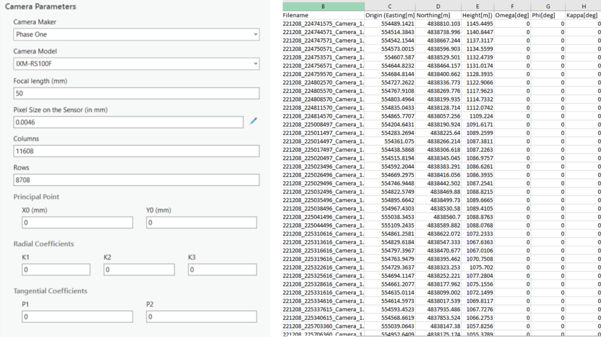
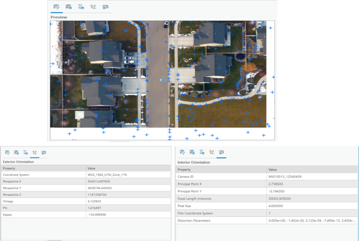
I use subset of aerial photos acquired with a Phase One iXQ100F camera in Boise. The focal length of the camera is 50mm and the pixel size is 0.0046mm. Each photo has dimensions of 11608 rows by 8708 columns. The camera used in this project is not pre-calibrated, meaning the precise interior orientation parameters such as focal length and principal points need to be computed. Additionally, location and orientation of the camera needs to be known we need to be know to calculate 3D locations of objects in photogrammetry. The information generally called exterior orientation parameters could be stored in the exif file of the photo or provided separately as it is in this case. The rotation values are set to zero (omega, phi, kappa) for the purpose of this demonstration. The camera parameters and exterior orientation information are illustrated in the figure below.
Workspace creation
With the interior and exterior orientation parameters determined, the next step is to create and configure an appropriate reality mapping workspace for the project. Detail documentation on orthomapping or reality mapping workspace in ArcGIS PRO can be found in this documentation.
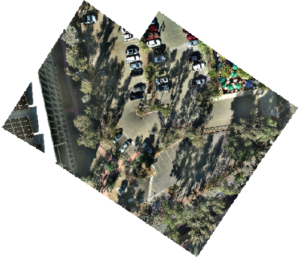
Using the location information from the orientation file, the photos are approximately located in the appropriate space. However, without the rotation values, the photos are not correctly oriented. Some of the images in the collection shown below are oriented in the opposite direction.
Block Adjustment
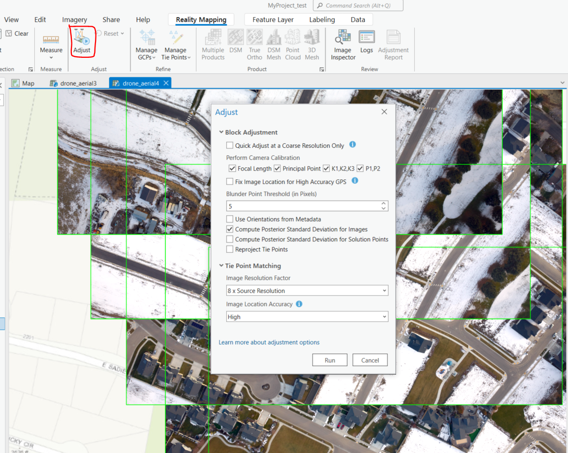
The subsequent task is to perform block adjustment, which involves detecting key points in the images and calculating tie points, which are common points in areas of image overlap. Using triangulation techniques, the camera positions and orientations are computed from these tie points.
After bundle block adjustment, the images are relatively oriented correctly but still slightly misaligned with the reference basemap, as shown in the illustration below.
The tie points and adjusted interior and exterior camera information can be examined using the image inspection tool. It can be observed that all the original interior and exterior values provided (camera model and orientation files) have been adjusted, except for the fixed parameter of pixel size. This is the primary goal of block adjustment without GCPs. The next step is to add GCPs to refine the adjustment and improve the absolute orientation.
Adding GCPs
ArcGIS PRO provides many options to add GCPs to photogrammetry projects. I will demonstrate all the possible ways to add GCPs to photogrammetric project. Check this link to read more on adding GCPs to photogrammetry workspace.
- import GCPs
This is perhaps the most common approach of adding GCPs and involves importing control points that have been collected before or after photo acquisition. In this scenario, control points have been collected prior to or after the photo acquisition. The control points after necessary processing are typically provided in csv format.
2. Manual
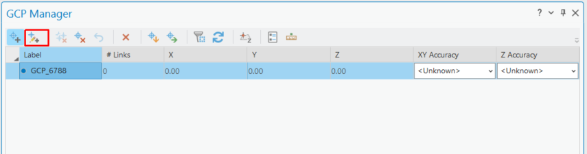
If the GCPs coordinates are known but not available in csv format, they can be added manually. This can be done by selecting the “Add GCPs manually” option in the GCP manager and entering the location information.
3. Adding GCPs from maps
If GCPs are not collected in the field but there are accurate basemap with identifiable features in the photos, the map can be used as GCPs for the project. The accuracy of the control points will depend on the accuracy of the basemap and the accuracy of matching the map and photo features. This method derives x and y location of the GCPs from the map and the Z information from the elevation source. It is important to specify any required transformation if the elevation source is of different coordinate reference system from the project.
4. Compute GCPs
The last option is to compute GCPs from reference images. This is more computationally intensive but could offer very high control points. And if the reference images are good, it could offer more accurate approach.
Refine Adjustment
After adding GCPS and rerunning block adjustment, the images are now absolutely aligned. At this point, further analysis and generation of required products can be carried out. For more details on how 3D models, building basemaps, and other products were derived from the data, please refer to this article.
Conclusion.
This article demonstrates the importance of bundle block adjustment and Ground Control Points (GCPs) in photogrammetry projects. By utilizing ArcGIS PRO, users can perform block adjustment, refine image orientation, and generate accurate photogrammetric products. The various methods for adding GCPs, including importing, manual entry, using maps, and computing from reference images, offer flexibility based on project requirements. Leveraging these techniques and tools enhances the accuracy and quality of photogrammetry results.